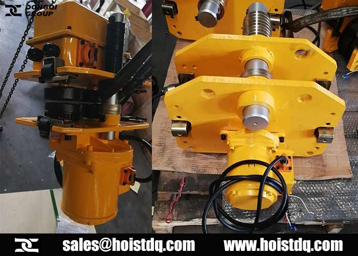
Install the trolley.
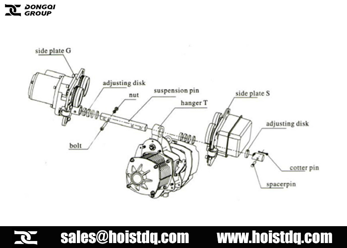
- Insert the suspension pin into the lateral plate G and lock it with suspension pin bolts and nuts.
- Install the suspension pin with adjusting disk.
- Install the suspension pin into the hanger T. The nameplates of electric hoist and trolley should be in the same direction.
- Install more gaskets into the suspension pin before insert it into the lateral plate S.
- Install the outside adjusting disk and spacerpin into the suspension pin, and insert the cotter pin into the spacerpin.
- When install the spacerpin, check if the cotter pin can be seen at the left side from the front of the trolley switch box.
Adjust width of the trolley.
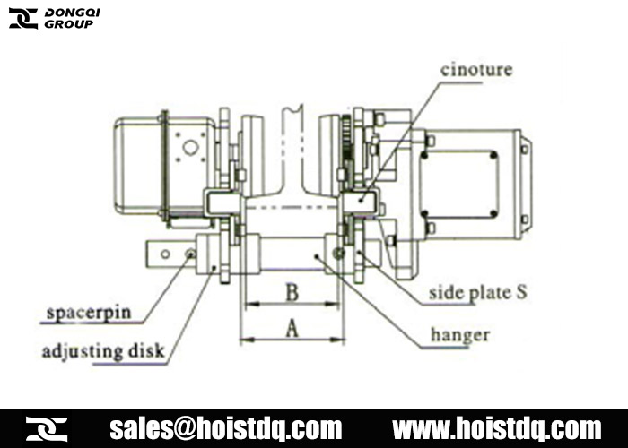
- Please adjust width of the trolley according to below drawing to get appropriate clearance.
- Size A is the dimension when two side plates stretch outside completely.
- Size A must be approximate B (the width of rail flange) +4mm.
- Please adjust size A by increasing or decreasing adjusting disk. Insert the cotter pin into the spacerpin and bend two branches of cotter pin if the size A is ok.
- The nut must be fixed and strong, insert cotter pin and bend it completely.
Install trolley into the beam.
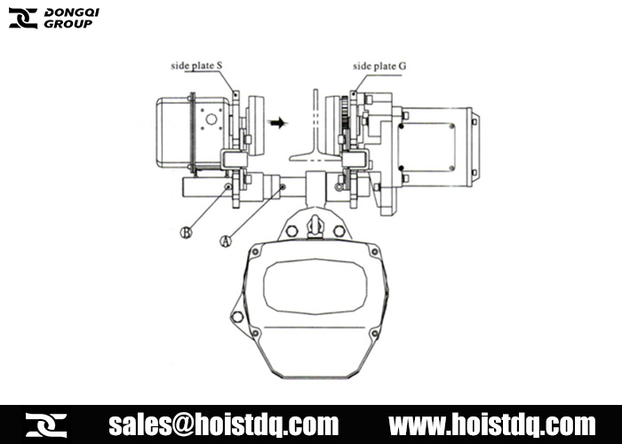
- Install the trolley at the end side of the beam and than slip the trolley which has been connected with hoist already to the appropriate place. This is the most convenient method.
- Unload the brake stopper from hole A on the suspension pin, and insert it into hole B. Insert cotter pin again and bend it completely.
- Pull the side plate S and G outside then lift the trolley untill the orbit wheel and orbit surface is in the same horizontal. Put the orbit wheel of side plate G onto the surface of the orbit.
- Hold the side plate G and stop it from dropping from the orbit. Push side plate S harder and put its orbit wheel onto the surface of the girder.
- Unload the brake stopper from hole B and insert into hole A. Do not forget to bend the cotter pin.
